mirror of
https://github.com/SoftFever/OrcaSlicer.git
synced 2025-08-05 21:14:01 -06:00
* Wiki + Readme: MD, security and improvements

Standardized MD GitHub Wiki format
Removed outdated and malicious links
Modularized calibrations
Suggested calibration order added
Minor bug fixes
Image improvements and corrections
Added winget commands
Completed previous WIPs
Added new WIPs
Removed obsolete references
Visual Changes

Co-Authored-By: Noisyfox <timemanager.rick@gmail.com>
Co-Authored-By: dewi-ny-je <2866139+dewi-ny-je@users.noreply.github.com>
Co-Authored-By: Nico Domino <7415984+ndom91@users.noreply.github.com>
Co-Authored-By: Martin Ulmschneider <7497782+mulmschneider@users.noreply.github.com>
Co-Authored-By: Rodrigo <162915171+RF47@users.noreply.github.com>

* MD Indentation + images update

---------

Co-authored-by: Noisyfox <timemanager.rick@gmail.com>
Co-authored-by: dewi-ny-je <2866139+dewi-ny-je@users.noreply.github.com>
Co-authored-by: Nico Domino <7415984+ndom91@users.noreply.github.com>
Co-authored-by: Martin Ulmschneider <7497782+mulmschneider@users.noreply.github.com>
Co-authored-by: Rodrigo <162915171+RF47@users.noreply.github.com>
77 lines
No EOL
6 KiB
Markdown
77 lines
No EOL
6 KiB
Markdown
# Pressure Advance
|
|
|
|
Pressure Advance is a feature that compensates for the lag in filament pressure within the nozzle during acceleration and deceleration. It helps improve print quality by reducing issues like blobs, oozing, and inconsistent extrusion, especially at corners or during fast movements.
|
|
|
|
Orca Slicer includes three approaches for calibrating the pressure advance value. Each method has its own advantages and disadvantages. It is important to note that each method has two versions: one for a direct drive extruder and one for a Bowden extruder. Make sure to select the appropriate version for your test.
|
|
|
|
> [!NOTE]
|
|
> [Adaptive Pressure Advance Guide](print_settings/calibration/adaptive-pressure-advance-calib.md)
|
|
|
|
> [!WARNING]
|
|
> For Marlin: Linear advance must be enabled in firmware (M900). **Not all printers have it enabled by default.**
|
|
|
|
> [!WARNING]
|
|
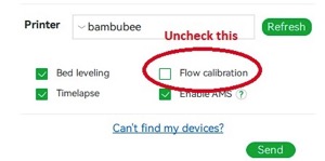
> For Bambulab X1/X1C users, make sure you do not select the 'Flow calibration' option when printings.
|
|
>
|
|
> 
|
|
|
|
## Line method
|
|
|
|
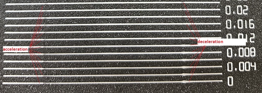
The line method is quick and straightforward to test. However, its accuracy highly depends on your first layer quality. It is suggested to turn on the bed mesh leveling for this test.
|
|
Steps:
|
|
|
|
1. Select the printer, filament, and process you would like to use for the test.
|
|
2. Print the project and check the result. You can select the value of the most even line and update your PA value in the filament settings.
|
|
3. In this test, a PA value of `0.016` appears to be optimal.
|
|
|
|
|
|
<img width="1003" alt="Screenshot 2022-12-31 at 12 11 10 PM" src="https://user-images.githubusercontent.com/103989404/210124449-dd828da8-a7e4-46b8-9fa2-8bed5605d9f6.png">
|
|
|
|
|
|
|
|

|
|
## Pattern method
|
|
|
|
The pattern method is adapted from [Andrew Ellis' pattern method generator](https://ellis3dp.com/Pressure_Linear_Advance_Tool/), which was itself derived from the [Marlin pattern method](https://marlinfw.org/tools/lin_advance/k-factor.html) developed by [Sineos](https://github.com/Sineos/k-factorjs).
|
|
|
|
[Instructions for using and reading the pattern method](https://ellis3dp.com/Print-Tuning-Guide/articles/pressure_linear_advance/pattern_method.html) are provided in [Ellis' Print Tuning Guide](https://ellis3dp.com/Print-Tuning-Guide/), with only a few Orca Slicer differences to note.
|
|
|
|
Test configuration window allow user to generate one or more tests in a single projects. Multiple tests will be placed on each plate with extra plates added if needed.
|
|
|
|
1. Single test \
|
|

|
|
2. Batch mode testing (multiple tests on a sinle plate) \
|
|

|
|
|
|
Once test generated, one or more small rectangular prisms could be found on the plate, one for each test case. This object serves a few purposes:
|
|
|
|
1. The test pattern itself is added in as custom G-Code at each layer, same as you could do by hand actually. The rectangular prism gives us the layers in which to insert that G-Code. This also means that **you'll see the full test pattern when you move to the Preview pane**:
|
|
|
|

|
|
|
|
1. The prism acts as a handle, enabling you to move the test pattern wherever you'd like on the plate by moving the prism
|
|
2. Each test object is pre-configured with target parameters which are reflected in the objects name. However, test parameters may be adjusted for each prism individually by referring to the object list pane:
|
|
|
|

|
|
|
|
Next, Ellis' generator provided the ability to adjust specific printer, filament, and print profile settings. You can make these same changes in Orca Slicer by adjusting the settings in the Prepare pane as you would with any other print. When you initiate the calibration test, Ellis' default settings are applied. A few things to note about these settings:
|
|
|
|
1. Ellis specified line widths as a percent of filament diameter. The Orca pattern method does the same to provide its suggested defaults, making use of Ellis' percentages in combination with your specified nozzle diameter
|
|
2. In terms of line width, the pattern only makes use of the `Default` and `First layer` widths
|
|
3. In terms of speed, the pattern only uses the `First layer speed -> First layer` and `Other layers speed -> Outer wall` speeds
|
|
4. The infill pattern beneath the numbers cannot be changed becuase it's not actually an infill pattern pulled from the settings. All of the pattern G-Code is custom written, so that "infill" is, effectively, hand-drawn and so not processed through the usual channels that would enable Orca to recognize it as infill
|
|
|
|
## Tower method
|
|
|
|
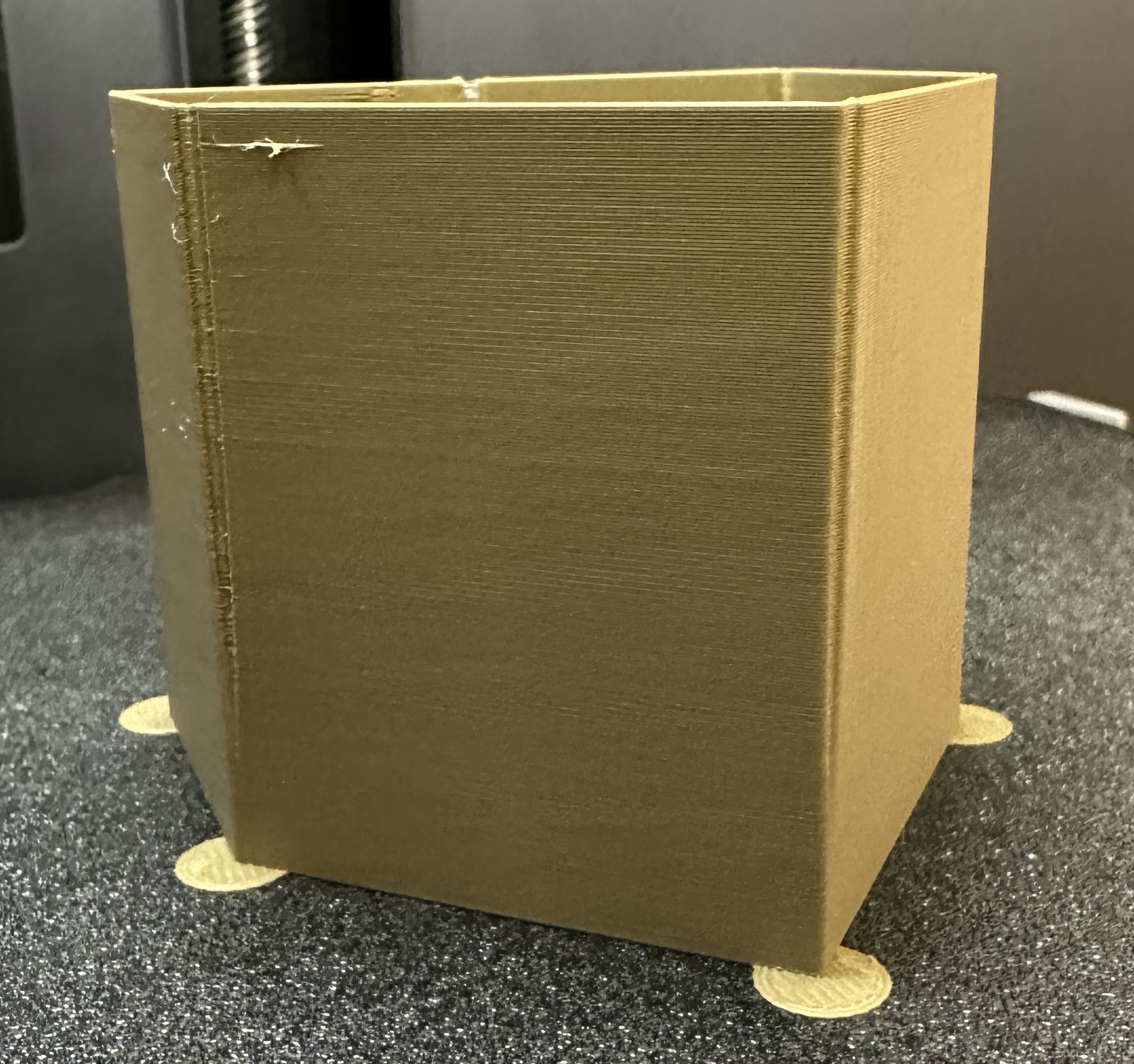
The tower method may take a bit more time to complete, but it does not rely on the quality of the first layer.
|
|
The PA value for this test will be increased by 0.002 for every 1 mm increase in height. (**NOTE** 0.02 for Bowden)
|
|
|
|
1. Select the printer, filament, and process you would like to use for the test.
|
|
2. Examine each corner of the print and mark the height that yields the best overall result.
|
|
3. I selected a height of 8 mm for this case, so the pressure advance value should be calculated as `PressureAdvanceStart+(PressureAdvanceStep x measured)` example: `0+(0.002 x 8) = 0.016`.
|
|
|
|
|
|
|
|
|
|
> [!TIP]
|
|
> @ItsDeidara has made a html to help with the calculation. Check it out if those equations give you a headache [here](https://github.com/ItsDeidara/Orca-Slicer-Assistant). |